

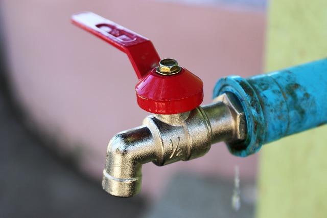
Maintaining the correct direction of fluid movement is a fundamental requirement in many piping systems. Water networks, industrial processing plants, pumping stations, and hydraulic installations all depend on controlled flow to operate safely and efficiently. When fluid moves in the opposite direction, it can damage equipment, disrupt processes, cause contamination, or create unwanted pressure changes. A one-way valve helps prevent these problems by allowing flow in the intended direction while restricting reverse movement.
One-way valves operate automatically in response to fluid pressure and flow conditions, making them valuable components in systems that require directional flow control. They are commonly known as check valves or non-return valves and are available in several designs for different applications. Understanding how a One Way Valve works, where it is used, and how to select the right type helps engineers improve pipeline reliability and protect connected equipment.
What Is a One-Way Valve?
A one-way valve is a mechanical device designed to allow fluid to pass in one direction and prevent or restrict flow in the opposite direction. Unlike manually operated isolation valves, it normally works without an external command or continuous operator intervention.
The valve contains an internal closing element that responds to pressure differences across the body. Depending on its construction, this element may be a disc, ball, flap, piston, or spring-loaded poppet.
When the pressure on the inlet side is sufficient to overcome the valve’s closing resistance, the internal element moves away from its seat and permits forward flow. When forward flow decreases or reverse pressure develops, the element returns toward the seat to close the passage.
One-way valves are commonly installed in:
- Pump discharge pipelines.
- Water supply and distribution systems.
- Wastewater treatment facilities.
- Hydraulic equipment.
- Compressed air networks.
- Chemical processing plants.
- Oil and gas installations.
- Heating and cooling systems.
Their main function is to maintain directional flow and reduce the risks associated with backflow.
How Does a One-Way Valve Work?
The working principle of a one-way valve is based on differential pressure. The pressure difference across the valve determines whether its internal closing element opens or closes.
1. Forward Pressure Opens the Valve
When fluid enters through the designated inlet, it applies force to the internal disc, ball, or other closing element.
If the forward pressure is greater than the cracking pressure and other forces resisting movement, the element moves away from the seat. This creates an open passage for fluid.
2. Fluid Passes Through the Valve
Once the valve opens, fluid travels through the available flow passage.
The pressure loss depends on the valve design, size, opening position, flow rate, and fluid properties. Some designs provide relatively low resistance, while others have more restrictive internal passages.
3. Forward Flow Decreases
When the pump stops or the flow rate falls, the pressure holding the closing element open becomes weaker.
Gravity, a spring, or changing pressure conditions can move the element back toward its seat.
4. Reverse Pressure Closes the Valve
If downstream pressure becomes greater than upstream pressure, reverse pressure acts on the closing element and pushes it toward the closed position.
The element contacts the seat, restricting reverse flow through the pipeline.
The effectiveness of this action depends on closure speed, seating design, operating conditions, and the condition of internal components. A standard one-way valve does not necessarily provide the same level of protection as a specialized backflow prevention assembly.
Main Components of a One-Way Valve
Although designs differ, most one-way valves contain several basic components that work together to control directional flow.
Valve Body
The body forms the main pressure-containing structure and provides the inlet, outlet, and internal flow passage. It may be manufactured from materials such as cast iron, ductile iron, carbon steel, stainless steel, brass, or other alloys.
Closing Element
The closing element moves in response to pressure changes. It may be a disc, ball, flap, piston, or poppet, depending on the valve design.
Seat
The seat provides the sealing surface against which the closing element rests when the valve is closed.
Seat materials may include metal or elastomers selected according to the fluid, temperature, pressure, and required leakage performance.
Spring
Some one-way valves use a spring to assist closing and maintain the element near the seat when forward flow decreases.
Spring characteristics influence cracking pressure and closing behavior.
Hinge or Guide Mechanism
Swing and flap designs use a hinge or pivot to guide movement. Lift and axial designs use guides to control the position of the closing element.
Cover or Bonnet
Depending on the construction, a cover or bonnet encloses internal components and may provide access for inspection or maintenance.
Common Types of One-Way Valves
Different one-way valve designs offer different operating characteristics. The most appropriate type depends on the fluid, flow rate, pressure conditions, installation arrangement, and required closure performance.
1. Swing Check Valve
<AsyncImage query=”industrial swing check valve cutaway hinged disc internal mechanism technical diagram” aspectRatio=”5:4″ width=”100%”/>
A swing check valve contains a disc attached to a hinge or pivot. Forward fluid pressure pushes the disc away from the seat, allowing flow through the valve. When flow stops or reverses, the disc swings back toward the seat.
Advantages:
- Relatively simple construction.
- Low pressure loss in suitable applications.
- Available in a wide range of sizes.
- Suitable for many water and industrial services.
Limitations:
- Closure may be slower than spring-assisted designs.
- Can experience valve slam under certain operating conditions.
- Installation orientation must follow manufacturer requirements.
Swing check valves are commonly used in water distribution networks, pump discharge lines, and industrial pipelines.
2. Lift Check Valve
<AsyncImage query=”industrial lift check valve cutaway sectional diagram guided disc” aspectRatio=”5:4″ width=”100%”/>
A lift check valve uses a guided disc or piston that moves away from its seat under forward pressure. When the forward pressure decreases or reverse pressure develops, the closing element returns to its seat.
Advantages:
- Guided movement of the closing element.
- Effective seating with suitable design.
- Available for selected high-pressure applications.
- Suitable for certain steam and process services.
Limitations:
- May produce a higher pressure drop than some other designs.
- Can be sensitive to contamination and deposits.
- Some configurations have specific installation orientation requirements.
Lift check valves are used in industrial process lines, steam systems, and selected utility applications.
3. Ball Check Valve
<AsyncImage query=”ball check valve cutaway diagram spherical ball internal seat industrial” aspectRatio=”5:4″ width=”100%”/>
A ball check valve uses a spherical closing element that moves away from the seat during forward flow. When the flow stops or reverses, the ball returns to block the passage.
Advantages:
- Relatively straightforward internal mechanism.
- Suitable designs can handle certain solids-containing fluids.
- Available in compact configurations.
- Maintenance can be straightforward where access is provided.
Limitations:
- Ball and seat materials must suit the fluid.
- Performance varies with ball movement and flow conditions.
- Not every model is appropriate for abrasive or highly viscous fluids.
Ball check valves are commonly used in wastewater systems, drainage applications, and selected fluid transfer installations.
4. Dual Plate Check Valve
<AsyncImage query=”dual plate wafer check valve sectional cutaway spring loaded plates technical illustration” aspectRatio=”5:4″ width=”100%”/>
A dual plate check valve contains two semicircular plates mounted on a central hinge or shaft. Forward flow pushes the plates open, while springs and reverse pressure help return them to the closed position.
Advantages:
- Compact and relatively lightweight design.
- Suitable for installation between pipeline flanges.
- Spring-assisted closure.
- Available for many industrial and water applications.
Limitations:
- Requires correct sizing and installation.
- Internal parts may need inspection.
- Performance depends on fluid characteristics and flow conditions.
Dual plate check valves are frequently used in water networks, HVAC systems, and industrial process pipelines.
5. Spring-Loaded or Silent Check Valve
<AsyncImage query=”spring loaded axial silent check valve cutaway internal poppet technical diagram” aspectRatio=”5:4″ width=”100%”/>
Spring-loaded check valves use a spring to return the closing element toward the seat when forward pressure decreases.
Some axial or nozzle-style designs are commonly described as silent check valves because their guided, spring-assisted movement can help reduce the impact associated with reverse flow.
Advantages:
- Spring-assisted closure.
- Can reduce valve slam in suitable systems.
- Available in compact designs.
- Useful in selected pump discharge applications.
Limitations:
- Spring selection influences opening pressure.
- Incorrect sizing may prevent full opening.
- Performance depends on flow velocity and pressure conditions.
These valves are often considered in pumping stations and systems where controlled closure is important.
Why Are One-Way Valves Essential in Piping Systems?
Reverse flow can create several problems in industrial and utility installations. A properly selected one-way valve helps manage these risks.
Protecting Pumps from Reverse Rotation
When a pump stops, water or another fluid in the discharge pipeline may flow backward. This can cause reverse rotation and place additional mechanical stress on the pump and its drive system.
A one-way valve helps prevent reverse movement through the pump by closing when forward flow decreases or reverses.
Preventing Backflow into Supply Lines
In water distribution systems, reverse flow may introduce unwanted fluid into upstream pipelines.
One-way valves help maintain directional separation, although applications involving potable water or contamination hazards may require additional approved backflow prevention devices.
Protecting Compressors and Other Equipment
Reverse flow can affect compressors, meters, filters, heat exchangers, and other connected equipment.
Installing a suitable valve helps prevent unwanted pressure and flow from reaching components that are not designed for reverse operation.
Supporting Parallel Pump Systems
Industrial and municipal pumping stations often use multiple pumps connected to a common discharge header.
Individual one-way valves can prevent fluid from flowing backward through an inactive pump when another pump is operating. Correct valve selection is important to avoid unstable operation and excessive pressure fluctuations.
Maintaining Process Direction
Chemical plants and manufacturing facilities often move fluids through equipment in a specific sequence.
A one-way valve helps prevent unintended flow between process stages, supporting the required direction of movement.
Applications of One-Way Valves Across Different Industries
One-way valves are used in many sectors because directional flow control is important for equipment protection and process reliability.
Water Supply and Distribution
Municipal water networks use one-way valves in pumping stations, treatment plants, storage systems, and distribution pipelines.
They help prevent reverse flow through pumps and connected pipe sections. However, drinking-water protection requirements must be assessed separately because a standard check valve may not meet the requirements for a certified backflow prevention assembly.
Wastewater Treatment
Wastewater facilities use check valves in pumping systems, drainage pipelines, and treatment equipment.
Ball check valves and other designs suited to solids-containing fluids may be selected depending on the wastewater composition and the likelihood of blockage.
Oil and Gas Industry
Oil and gas facilities use one-way valves in production lines, pipeline systems, processing equipment, and auxiliary services.
Material compatibility, pressure rating, temperature limits, and closure performance are important factors in these applications.
Chemical Processing
Chemical plants use one-way valves to prevent unwanted reverse movement between connected process systems.
Valve body, seat, and sealing materials must be compatible with the handled chemicals and expected operating conditions.
HVAC and Cooling Systems
Heating, ventilation, and air-conditioning systems use one-way valves to prevent unwanted circulation through inactive pumps or alternative flow paths.
They are commonly considered in chilled-water, heating-water, and cooling circuits.
Hydraulic Systems
Hydraulic installations use check valves to maintain directional flow and help protect components from reverse pressure.
They may also be used in specialized arrangements to maintain pressure or prevent unwanted movement, depending on the circuit design.
Compressed Air Systems
Compressed air networks use check valves to prevent air from returning toward compressors or other equipment when pressure conditions change.
The selected valve must be compatible with the operating pressure, air quality, flow capacity, and installation environment.
Key Factors to Consider When Selecting a One-Way Valve
Choosing the correct one-way valve requires evaluating the complete operating environment rather than relying only on pipeline size.
1. Fluid Type and Properties
Identify whether the system carries water, oil, gas, steam, chemicals, wastewater, or slurry.
Consider the fluid’s viscosity, chemical composition, temperature, density, and suspended solids. These properties influence the valve design, body material, seat material, and internal clearance requirements.
2. Operating Pressure
Check the normal and maximum operating pressures, including possible pressure surges.
The valve must be rated for the expected service conditions. Pressure ratings may vary with the selected material, design, and operating temperature.
3. Flow Rate and Velocity
The valve must open reliably at the available flow rate.
An oversized valve may not achieve sufficient opening under low-flow conditions, while an undersized valve can create excessive pressure loss.
Review manufacturer flow data and recommended operating ranges before selection.
4. Cracking Pressure
Cracking pressure is the minimum pressure difference required to begin opening the valve.
This factor is particularly important in systems with low pump pressure or limited available differential pressure.
Spring-loaded designs may require a higher opening pressure than gravity-assisted designs, depending on their construction.
5. Closure Speed and Water Hammer
When flow stops or reverses, the valve must close appropriately.
A valve that closes too slowly may allow significant reverse flow before seating. Rapid closure can also create pressure transients in certain systems.
Engineers should consider pipeline length, fluid velocity, pump shutdown characteristics, and transient pressure behavior when choosing the valve.
6. Installation Orientation
Some designs can be installed in horizontal or vertical pipelines, while others have specific orientation requirements.
Gravity-operated valves are particularly dependent on installation position. Always follow the manufacturer’s installation instructions.
7. Material Compatibility
The body, closing element, seat, spring, and seals must be suitable for the fluid and environment.
Common body materials include cast iron, ductile iron, carbon steel, stainless steel, brass, and bronze. Seat materials may include EPDM, NBR, PTFE, or metal, depending on the application.
8. Maintenance Requirements
Consider whether the valve can be inspected or serviced without extensive pipeline modifications.
Applications with contaminated fluids may require more frequent inspection, accessible covers, or designs that reduce the likelihood of blockage.
One-Way Valve vs. Other Common Valve Types
Although several valves are installed in the same piping systems, they perform different functions.
| Valve type | Main function | Operating method |
|---|---|---|
| One-way valve | Prevents or restricts reverse flow | Automatic pressure-responsive operation |
| Gate valve | Isolates a pipeline | Linear gate movement |
| Ball valve | Provides on/off isolation | Quarter-turn rotation |
| Globe valve | Regulates flow | Movable plug or disc |
| Butterfly valve | Provides isolation or selected flow regulation | Rotating disc |
| Control valve | Regulates process variables | Actuator-controlled movement |
A one-way valve is not intended to replace a manual isolation valve. Many installations use both: the check valve maintains directional flow, while an isolation valve allows the pipeline section to be shut off for maintenance.
Common One-Way Valve Problems and Their Solutions
Like other mechanical components, one-way valves can experience wear, blockage, and operating difficulties.
| Problem | Possible cause | Recommended action |
|---|---|---|
| Reverse leakage | Damaged seat or trapped debris | Inspect and clean or replace sealing components |
| Valve slam | Slow closure or unsuitable flow conditions | Review valve design and system transients |
| Excessive pressure drop | Incorrect sizing or restricted opening | Check flow requirements and valve specifications |
| Failure to open | Insufficient pressure or obstructed closing element | Verify cracking pressure and inspect internals |
| Noise and vibration | Unstable flow or mechanical wear | Evaluate flow conditions and component condition |
| External leakage | Damaged seals or connection joints | Inspect and replace defective components |
Recurring problems may indicate that the valve type or size is unsuitable for the actual operating conditions.
Installation and Maintenance Best Practices
Correct installation and regular inspection help maintain reliable operation throughout the valve’s service life.
Installation Guidelines
- Check the flow direction arrow marked on the valve body.
- Confirm the valve’s permitted installation orientation.
- Clean the pipeline before installation.
- Ensure connecting pipes are properly aligned.
- Use compatible gaskets and connection materials.
- Follow manufacturer recommendations for installation clearances.
- Avoid placing the valve where access for inspection is restricted.
- Inspect the installation during commissioning to verify correct operation.
Maintenance Guidelines
- Inspect the body and pipeline connections for leakage.
- Monitor unusual noise, vibration, and pressure changes.
- Check the internal closing element for free movement.
- Inspect the seat and sealing surfaces for wear or deposits.
- Examine springs, hinges, and guides where fitted.
- Clean or replace components according to manufacturer instructions.
- Maintain records of inspections and repairs.
Before servicing a one-way valve, isolate the relevant pipeline section, release stored pressure, and follow the site’s safety and lockout procedures.
Conclusion
One-way valves are essential components in piping systems where reverse flow could damage equipment, disrupt processes, or compromise fluid quality. Their automatic operation allows fluid to move in the intended direction while restricting movement in the opposite direction.
Swing, lift, ball, dual plate, and spring-loaded designs offer different advantages for water distribution, pumping stations, industrial processing, hydraulic systems, and other applications. Selecting the right type requires careful consideration of fluid properties, pressure, flow rate, cracking pressure, closure behavior, installation orientation, and material compatibility.
With appropriate sizing, correct installation, and regular maintenance, one-way valves help protect connected equipment and support dependable operation across a wide range of industrial and utility systems.
About Post Author




More Stories
Why Regular Audit Services Are Essential for Effective Risk Management
What Makes a Good O-Ring Seal Supplier for High-Performance Applications?
Key Benefits of Wind Power Oil Immersed Transformers in Renewable Energy Systems